Installing a SSB radio and KISS

Sometimes, I think KISS is the best solution.

We finally purchased an ICOM 802M SSB radio and AT-140 antenna tuner for better or worse. If you are not familiar with the radio, the radio has a remote head and speaker, hence the transceiver can be mounted in “almost” any location. Now the challenge is to find a location to mount the transceiver and antenna tuner without losing too much storage space. In an effort to “do things right” I telephoned ICOM and discussed mounting locations. The ICOM technician was helpful and polite but strongly recommended I employ a marine professional who was very experienced at installing SSB radios and antenna tuners.

ICOM recommended a location that has at least 1 ft of space around each of the sides of the unit, as well as the top. This is to allow sufficient air space for the heat generated by the transceiver to disperse without overheating the unit. Further, the two modules - transceiver, tuner - and cables should not be located too close to other DC wiring or instrument cables. ICOM pointed out the units and their associated cables may cause feedback into other instruments and radios via the DC wiring or other instrument cables. The engine compartment is not recommended because it is hot and RF from the alternator may cause noise in the radio. It was also recommended I read the NMEA standards for installing SSB radios, &C. According to the technician, these were available online. I checked NMEA’s website (http://www.nmea.org/) and for a cost of $270 and $340, I may purchase the standards. Based on my conversation with ICOM, it seems near impossible to install the radio and tuner within the space of a small boat under let’s say 50 ft LOD. Of course, ICOM did admit, sometimes one has to compromise. Unfortunately, the ICOM manual does not include these installation recommendations.

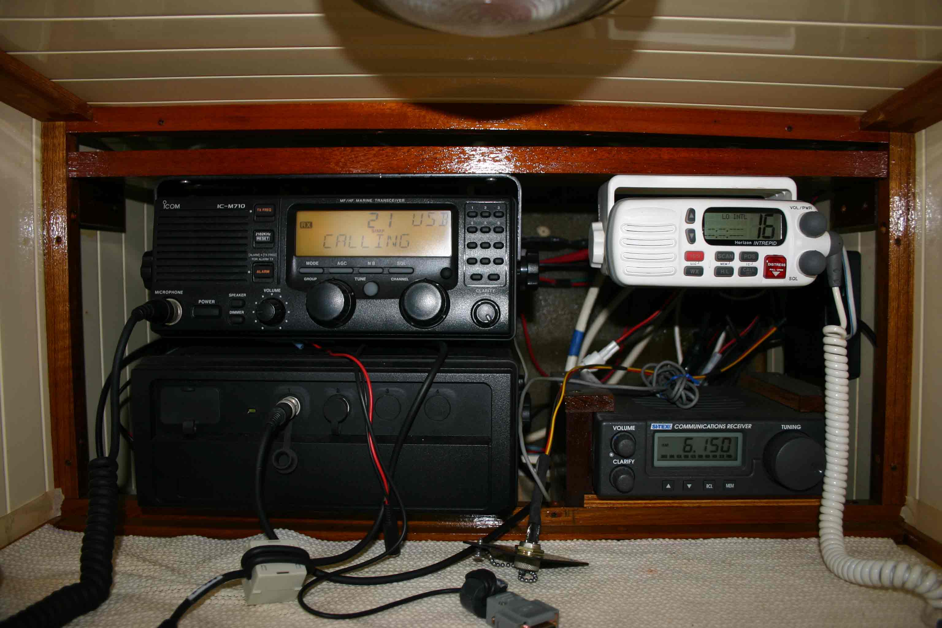
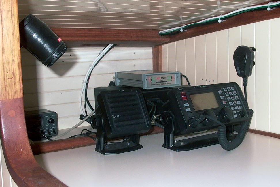
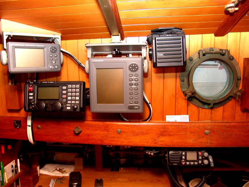
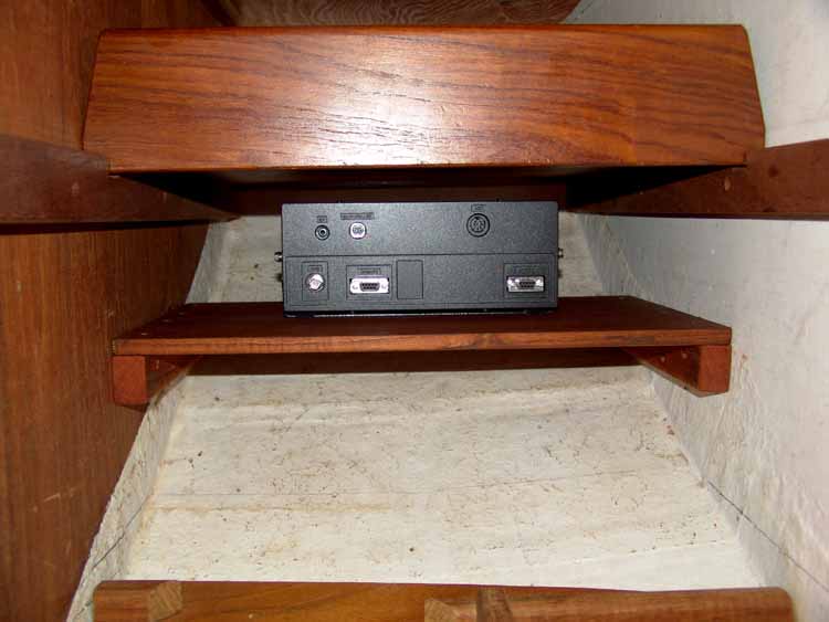
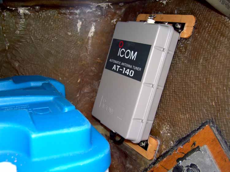
My SSB installation on IDUNA will be as follows. The antenna tuner will be mounted on the starboard side of the transom inside the lazaretto. This will place the tuner about 1 ft from the battery box, approximately 2 ft from the battery cables and at least 3 ft from the fluxgate compass head. I may need to move the fluxgate head, if I detect any interference when transmitting. The remote head and speaker are already mounted on the side of the cabin above the chart table. I will mount the transceiver below the chart table - (note: IDUNA’s interior is different than found on a SLM boat - Canadian BCC). Routing the cables will be a compromise, in terms of DC wiring and other instrument cables , as I suspect it is on most boats.

I am always amazed how electronic components seem so simple in principle to install become so complicated in practice. If I would have known all of the above before I went to the Annapolis boat show, I would have reverted back to KISS-MA principle when we visited ICOM’s booth.

If you have a SSB radio installed in your Bristol Channel Cutter, I am interested how you solved the space limitation and ICOM recommendations when you installed your radio and tuner. In addition, how well does your transceiver work when transmitting and receiving?

Fair Winds,

Rod

Rod: Hi!

Zygote has an ICOM IC-M710RT SSB radio (with a remote head) and an ICOM AT-130 antenna tuner, feeding an insulated portion of the backstay as antenna, all installed by Sam L Morse Co.

Zygote’s antenna tuner is, similar to yours, mounted in the lazarette, on the starboard side (along with an inverter/charger).

Zygote’s SSB transceiver and remote head are mounted above the chart table (along with the VHF transceiver, an AM receiver, and a SeaTalk/NMEA/PC converter.

The transceiver and remote head are mounted with the remote head vertically above the transceiver. I’ll take a digital photo in the near future and post it.

Zygote’s separate SSB transceiver and remote head allow easy direct connection for connecting our laptop PC and Pactor modem (for NAVTEX, weather fax, and e-mail). The all-band AM receiver provides redundant backup (ie it can tune all bands and can connect to the PC for weather fax and NAVTEX reception).

Counterpoise (grounding) is provided by a 3" wide strip of copper foil running from the lazarette forward to the lead ballast and connected to the starboard boomkin stay and other metallic objects.

The SSB and antenna tuner feed the transmission signal to the insulated portion of the backstay, which acts at the antenna. The antenna comprises 3.3 metres of GTO-15 wire and 8.7 metres of the backstay, for a total length (or aperture) of 12 m. Theoretically, the ATU may be expected to have problems tuning frequencies in the 12 MHz (24 metre) and 25 MHz (12 metre) bands because of antenna resonance, but we’ve had no problems. The bottom end of the antenna portion of the backstay is 2.84 m above the waterline and 2.0 m above the cockpit deck. The backstay slopes at an angle to the horizontal of 63?. The distance from the bottom end of the antenna to the head of a person seated in the cockpit, at the tiller, is 1.25 m at an angle of 111.5? from the run of the antenna.

The antenna radiates considerable energy. I’ve numerically modelled the radiation received in the cockpit (Zygote is registered in Australia, one of the more bureaucratic nations around, and so we have requirements on documenting the electro-magnetic radiation; we meet their standards for radiation safety) and we try to keep to the one metre rule (ie keep at least 1 m away from all parts of the antenna when we’re transmitting). Pactor modem transmissions are much more energetic than voice transmissions, but they are of short duration.

Our tx and rx are fine - as good as any boat to which we’ve compared ourselves.

Our electronic compass transducers are (1) under the cabin sole and (2) in the forepeak. They are not affected by SSB tx. But our GPS antenna is on the boomkin and its data cable runs within a few centimetres of the GTO-15 wire. So our GPS data is lost during a tx (both a voice tx and a Pactor tx).

A Pactor tx disturbs either of our autopilots (we run either an Autohelm ST4000 GP on the tiller or an ST1000 on the rudder trim tab). We’ve added ferrite suppressors (and have more to add in the hope they might dampen the electromagnetic pulse), but it’s not too hard to steer manually when making a Pactor tx.

Cheers

Bil

Bil:

Thanks ever so much for your very informative detailed post. Based on the contents of your message, there is hope for IDUNA’s SSB installation. I suspect, we will experience some feedback problems but we will learn to live with that as I suspect, many others do.

I sent ICOM an e-mail and attached a copy of my post. I only felt it was fair to give them an opportunity to post a reply.

Kind Regards and thank you so very much.

Fair Winds,

Rod

Rod: Hi!

Attached is a quick photo of Zygote’s radio shack (Zradioshack.jpg, about 190K).

I’ve removed a fascia that normally is screwed in place (you can see the screw holes) and, to remove the fascia, I’ve removed the mike holders. You can see the hull, behind the radios.

Without the fascia you can see how the ICOM IC-M719RT is mounted: the remote head is mounted to a wooden strut above, while the transceiver is mounted on the chart table.

The vertical gap between them is small, only a few centimetres. The SSB transceiver loses heat to the air space around it. Our ambient air temperature varies from 24 - 34 degrees Celsius (something like 74 to ninety-something F, I’d guess). We’ve had no problems from overheating or radio interference (apart from the E-M pulse when making a Pactor Tx, described in my earlier post, which disturbs the autopilot).

The ICOM IC-M710RT is connected directly to our battery bank (that’s per the ICOM installation manual). So even when the ICOM SSB is not turned on, it has a parasitic current draw of perhaps 100 - 200 milliamps (I’ve never bothered to nail it more accurately than that). One radio tech warned me that SSBs so connected are prone to damage from voltage spikes, such as when charging the battery bank. I have contemplated putting a voltage regulator on that line, but haven’t got to the job yet (my job list has 49 chores and has been stable at that number for a few days). We’ve charged our battery bank via engine, genset, and shore power over the past 5 years without any sign of a problem. The ICOM IC-M710RT - which has been discontinued for a few years - is a v good unit in my estimation.

Cheers

Bil

Bil:

Thanks for the image of Zygot’s communication center. When I complete the installation of IDUNA’s SSB, I will post images.

I was unaware of the parasitic current draw. I suspect ICOM’s SSB memory circuit is the cause. I will connect the transceiver directly to the battery per ICOM’s recommendation but have not decide whether to install a switch or not. According to ICOM, a capacitor in the radio will maintain the memory for up to a week but it would be a shame to lose one’s favorite bands. A current draw of 100-200 milliamps equals about 2.5 to 5 amps per day to maintain the radio’s memory.

The information you provide is of immense help and gives me hope that regardless of ICOM’s narrow guidelines, SSB radio’s do work on a small boat, perhaps not 100% perfect but most boat seem to have go RX and TX, as well as experience some feed back.

Even the professional don’t always get it right. One of our cruising friends reports that when he transmits, all the instruments, radios, nav equipment “light up.” The boat’s 802M and antenna counterpoise weres factory installed by the builder of rather expensive cruising boats.

As with most decisions on a boat, compromise seems to be the solution. Wow, perhaps cruising boats would be a good training experience for the world’s politicos.

Bil, thanks for you help. If there is anything I can do for you, let me know.

Kind Regards,

Rod

Bil & Rod,
I’m in the latter stages of installing a new ICOM802 & AT140 in Itchen. Simple enough in principle but the very devil of a task to do it neatly in an older boat with lots of cabinetry and pre-existing wiring to work around. I’ve put the control unit and speaker in the cabinet to the right of the cabin heater above the forward end of the stbd settee. That way I can sit next to it and also have the cabin table close-by for operating manuals, lists of net frequencies, logbook, & mug of coffee or rum depending on tme of day. There was plenty of space for it there and seemed more convenient than standing in front of the refrigerator/nav station where the VHF is already mounted.

The transceiver I bolted under the quarterbearth just aft of the refrigerator with ground strap glassed onto the hull and routed down and forward to the lead ballast and also to the aft stainless water tank. It also leads back to the AT140, which is fastened to the transom, centered just under the deck.

I’ve yet to rig insulators to the backstay but have temporarily rigged about 4 meters of GTO15 and enough speaker wire to almost reach the masthead as a temporary antenna to test things out. Reception seems quite good but I have no standard of comparison – Bahamas, Worldnet, BajaNet were strong last evening.

I have not yet tried transmitting, for fear of inadvertantly stepping on a Ham band. I’ve found the ICOM 802 manual to be rather strange and unintuitive in organisation. As it came from the factory, my unit is pre-programmed with channels and (unless I have missed something obvious) does not allow direct keypad entry of frequencies. There must be a way, but how? Or, why not?

So here are a couple of questions:

  1. Backstay insulator installation; My caliper gives a wire size of well over 1/4" and a hair under 9/32". For a Norseman insulator, is this a close enough nominal measurement for the correct choice of fitting to be 9/32"?

  2. Is there someone on the BCC list with some experience using an ICOM 802 who would be willing to give some practical advice on basic marine band transmission operation?

Regards to all,

Scott

Scott: Hi!

I can only address Q1, because my experience is with an earlier iCOM model.

My guess is that you have 9/32 wire rope as your backstay - remember that you have to measure the diameter of wire rope across the strands, not across the valleys between the strands (if that makes sense!).

Cheers

Bil

Attached is a photo of the Icom M802 installation in Adventure. The control head and speaker are positioned on the nav table/ice box lid to allow it to open fully.

The AT-140 tuner is on the starboard side of the transom inside the lazarette. The ground plane was installed at SLM and consists of two solid copper wires running in parallel from a bus at the AT-140 tuner location to the ballast. The wires appear to be about 14 gauge and are about 3 inches apart. The boom gallows stanchions are tied to the ground plane and through them, the lifelines as well as the stainless steel water tank.

The antenna is constructed from 12 gauge Ancor wire and is hauled up by a 1/8? Spectra halyard. (I do not like insulated backstays plus copper radiates better than stainless steel).

I did not wire the radio directly to the battery but installed a 30 amp breaker and 10 gauge wire which can handle the 30 amp load. I?m not sure what wiring the radio directly to the battery will accomplish if the circuit is sized correctly. If it is wired directly to the battery, then there is a current draw even if the radio is switched off. This is not to maintain the contents of memory but rather an oscillating crystal heater. Icom says that if power is removed from the radio then it takes 5 minutes for the oscillator to be temperature stabilized at the next power up. I prefer this to the radio being wired directly to the battery.

I agree about the M802 manual being rather nebulous and it does not completely discuss how to program the frequencies. Here is a link to instructions on how to do the programming: www.icomamerica.com/dealersonly/ic-m802_freq_prog.pdf

In order to program the M802, it must be in ?Open Mode?. To put the M802 in ?Open Mode?, start with the radio turned off. Press and hold down the 2, mode and TX keys simultaneously and then turn the radio on while holding the keys down.

Scott:

I discussed installing SSB with a friend who has a good understanding of radio communications and is also a triple-sigma type of guy. His basic advice was to install the unit, and hunt down the gremlins as they appear. Most installation have some type of feedback and you learn to live with it. Some SSB operators will shut down the nav-equipment when they are transmitting. His advice was to “try” to keep the SSB cabling and wiring away from the other cables and wires in the boat - do the best you can. Ferrite rings and grounded shield braid (tin plated copper tubular braid sold in radio equipment stores) can be used to reduce feedback. The boat’s electrical ground and radio ground should be separate.

Cruising Club of America has several excellent articles on SSB - http://www.cruisingclub.org/ . Select the link “Offshore Communication and Electronics.” The articles are in pfd format and are well written. ICOM also has a free downloadable version of Gordon West’s Book, “Marine SSB Single Sideband Simplified” in pfd format - http://www.icomamerica.com/marine/ssb_book.asp .

If all else fails in our efforts to communicate at sea I will just have to invest in a professional set of signal flags and one signaling cannon and rename our boat to HMS Surprise.

Fair Winds,

Lord Nelson

John, Bil and Rod,
Thanks for all your info. Yes, I just went ahead and wired directly to a substantial lug on the switched side of the Guest rotary main disconnect switch. Somewhere in the ICOM 802 literature, in addition to recommending a direct battery connection, they point out that this may result in a dead battery if the boat goes too long between battery charges. There is an oscillator heater that is “always on” so that the transceiver will be frequency-stable fron an otherwise “cold start”. Is this perhaps the “parasitic current draw” noted by Bil? Elsewhere in the literature ICOM allows as how a direct battery connection is not really necessary so long as the wire run is not too long and the wire gauge is adequate. Since the run is short I took that route for the moment.

A closer look at the ICOM 802 Quick Reference & Channel List shows a bunch of marine band 4 and 8 kH frequencies assigned to Channels C1-xx and C2-xx with the expected 3kHz increments. So that eliminates the reason for some of the frequency programming I thought I needed to do. And, the need to go to Open Mode is clearly the answer to my puzzlement over being unable to enter frequencies into user defined channels. Strangely uninformative manual – just the basic facts with no hand-holding and few helpful hints, other than the good appendix on antennas and ground planes.

I’ll try some transmissions tomorrow and see how it does. I’ve been impressed with the amount of semi-conflicting information on antennas, ground planes, battery connections and cable connections. Makes me think that any half way decent setup will work, but that boats and expectations differ. I agree with Rod that some experimentation will be the way to go to maximize quality. I expect to get some interference with noise from other equipment on Itchen - Adler Barbour refrigeration units got a savage roasting in a bulletin board posting from a waterway net ham operator. If so I will be looking at ferrites and shielding and cable rerouting – or just turn the refrig off when listening to weak signals or transmitting.

Scott

The attached image shows IDUNA’s nav-station. Deciding where to place the control head of the SSB radio and other navigation instruments is always a compromise between a clean neat built-in installation and functional efficiency.

I will post other images of the transceiver and tuner installations as they become available.

Rod
BCC IDUNA

Transceiver and Tuner Intallations:

The attached three images show the transceiver and turner mounted in their respect comparments. The first image (copy 1) shows the pots and pans cabinet located below the chart table. The transceiver (image copy 2) is mounted in this cabinet on a new fixed shelf installed below an existing sliding upper shelf. The turner is mounted on the starboard side of the transom aft of the starboard battery box (image copy 3). The two glassed Baltic plywood mounting plates epoxed to the hull were fitted with stainless steel T-nuts. The turner is bolted to the mounting plates with 1/4 X 20 stainless steel boats coated with lanolin.

DSC03127 copy 1.jpg

Rod: Hi!

Nice pics!

I forgot to pick up your inquiry about NMEA - I hope you didn’t buy the full NMEA specs.

I suggest you get the free NMEA techdata document from the old Yacht-L listserver.

To do that, send an e-mail to:

LISTSERV@NIC.SURFNET.NL

Leave the subject line blank.

In the body of the e-mail, put:

GET NMEA0183 TECHDATA Yacht-L

Then wait about as long as it takes to drink a glass of water and check your mail.

You can get an index of all the retrievable docs from the Yacht-L archive with the following e-mail body:

GET YACHT-L FILELIST Yacht-L

Cheers

Bil

Bil:

You are a wealth of valuable information. Thank you for the link. I did not purchase the NMEA specification documents. Besides the price, I think Scott was right when he wrote, “Makes me think that any half way decent setup will work.”

I downloaded the watch duty document you wrote. It is worth the read and would well serve a crew member who has never stood a watch offshore or on a coastal passage. Standing watch is serious business, especially when sailing near busy shipping lanes.

Fair Winds,

Rod

Rod, you’ve gotten excellent advice, and I can’t add much other than:

  1. I used the same lazarette/transom location as many of the other repliers. It was convenient to the copper strap and the new thru deck fitting for the antenna cable.

  2. I also mounted our M802 remote head and speaker in a cabinet outboard of the icebox.

  3. I mounted the tranceiver inside the stbd cabinet below the bookshelf just forward of the icebox. There is NOT 1 foot of space in any direction, although SLM did provide one of their small vents near the radio. I think that for our applications of e-mail, weatherfax, and the occasional net-control responsibilities we take on, ventilation is adequate. We’re rarely transmitting for more than 30 seconds continuously, and for e-mail, it’s only a few seconds per minute, so it’s not really heavy duty use.

  4. I decided that a continuous battery draw was not in the best interests of our “cruising sailboat” electrical system, and installed a separate 30 amp breaker for the SSB. I don’t know what temperature the 802 keeps its crystal at, but it wouldn’t take long to bring it to temp in the areas we’ve been cruising.

  5. The ground plane that SLM installed in Galatea and the 802/A140/Pactor IIPro combo has worked very well for us, and we generally put out a very good signal.

  6. The only problems we’ve had are what I think are early production problems in the auto-tuning section of the radio, which have been documented on the Sailmail website. It took us a while to realize that we had those problems and the radio is now in the shop to confirm our diagnosis and get the firmware updated to deal with the issue.

Good luck with your installation.

Tom
SV Galatea

Well Itchen’s SSB is installled and reception is good, and I’ve gotten some very clean weatherfax downloads to my laptop using JVcomm32 software. BUT there is terrible interference from the Sony VAIO laptop’s “power brick” unless I pull the power plug and run the laptop on battery power alone. Big time nuisance. Anyone have any suggestions on reducing RF interference from laptop charger bricks? Yes, I know,buy a pile of extra laptop batteries . . . … The old Raytheon RL9 radar set is even worse, but the laptop problem is more annoying at the moment. As luck would have it, my worries about the Adler Barbour refreigerator turned out to be unfounded - no RF noise worth mentioning. I’ll post the laptop question to rec.boats.electronics and see what suggestions I get.

Scott

Itchen Wrote:
I expect to

get some interference with noise from other
equipment on Itchen - Adler Barbour refrigeration
units got a savage roasting in a bulletin board
posting from a waterway net ham operator. If so I
will be looking at ferrites and shielding and
cable rerouting – or just turn the refrig off
when listening to weak signals or transmitting.

Scott

Scott: Hi!

Interference from the laptop AC transformer or the inverter supplying it with AC?

Most laptop transformers I’ve seen have a ferrite suppressor close to the laptop end of their output cord. If yours doesn’t already have a ferrite there, adding one (and perhaps threading the output cord through and around the ferrite more than once) is worth a try.

Cheers

Bil

Scott, we’ve been using a DC to DC voltage converter to power our laptop. Ours was made by a ham in Florida who custom builds them to match the voltage requirements of your laptop. The only problem is that I can’t remember the name or callsign of the guy, or even enough specifics to find him on the web, and all our info is in Oz on the boat. I heard about him from another cruiser in the Sea of Cortez. In 2002 our cost about $69. He also sells the components and plans if you’d like to build it yourself, (costs less).

The two main benefits of his unit are that a DC to DC converter is more efficient than running your inverter, and as a ham, he understands the need to build the converter with minimal RF noise. We don’t have any problems with interference.

There are many DC-DC converters on the Internet, but if I somehow come across his address, I’ll get back to you.

Tom
SV Galatea

Hi

I am in the process of making a decision to install a SSB on my BCC (96) and was wondering if anyone had information regarding the factory installed copper foil, its connection to the lead keel and what other things that it may be connected to, ss water tanks etc. Has anyone used this as the counterpoise with no other modifications?? I have a sat phone and wonder if it is worth the $ & trouble??

Curious in the Quahog Republic

Sid
SV Arethusa

Hi Sid,
I recently installed a SSB with a KISS counterpoise system. Check it out at:
http://www.kiss-ssb.com/about.html

David Kent
s/v Rose