Removable Tiller?

Ahoy Team,

We’re currently replacing our rudder cheeks, which had some rot. Currently our tiller is held in place by a carriage bolt, which is fine…but since we’re replacing our rudder cheeks (and have a new tiller ready) we’re thinking about using something else to make it easier to remove the tiller.

I was thinking about a long clevis pin, but they’re a little hard to find. This is the best I could do since the rudder plus cheeks are about 5 1/2 inches wide:

I’m wondering if anyone else has an easily removable tiller and what design you might use to accomplish this.

Thanks always for the help and ideas.
Cheers,
Mike
CYMBA
BCC #77

Hmm … do you have a photo of your current tiller set-up, Mike?

I say that because Z and all the BCCs with hull numbers 9x - 1xx with which I am familiar have tillers that are v easy to remove.

I could not discover a photo of Z’s tiller set-up, so here is my clumsy attempt at a description:

The aft end of the tiller fits snugly into the tiller mortise. The tiller mortise (which some call a rudder mortise) is a rectangular aperture formed on each side by a rudder cheek, on the top by a block of timber I’ll call the rudder cap, and on the bottom by the body of the rudder.

The lateral surface of the tiller mortise, i.e. the inner surfaces of the rudder cheeks, are lined with a sheet of nylon.

The tiller is limited from moving further aft through the tiller mortise by two small timber cleats attached by screws to the tiller: one cleat on each side.

With the tiller home in the tiller mortise - i.e. with the cleats touching the rudder head - about 40 mm of the tiller protrudes, aft of the rudder head.

Drilled through that protruding portion of the tiller is a hole, about 4 mm in diameter (I’m guessing. I’ve never measured the hole diameter).

After pushing the tiller home into the tiller mortise (I usually smear silicone grease on the sides of the tiller so it slides smoothly and easily into the tiller mortise; petroleum jelly, KY jelly, etc might be just as good for all that I know), I insert the tiller retainer into that 4 mm hole.

The tiller retainer on Z is nothing more than a length of small stuff (i.e. small diameter cordage. Venetian Blind cord in polyester is what I use). I already have a figure-8 knot made in one end of the tiller retainer. The length of VB cord is such that after pushing it through the hole, there is enough for me to make yet another figure-8 stopper knot.

And that’s it.

My local on-line supplier of VB cord only has 2 mm VB cord in boring white. At 3 mm and above, they have sexier colours such as blue and black (but always monochrome, never a multi-colour. YMMV as to the colour range available near you.

The price for a reel of VB cord is outrageous, but I can afford a new tiller retainer cord every few years. You likely will have to find your own retailer of VB Cord. For my local on-line retailer, see: https://www.marinewarehouse.com.au/vb-cords

Bil,

First, I just have to say a huge thank you! Although we’ve only owned our BCC for a few short years - you’ve answered what seems like dozens of my questions and provided a true wealth of knowledge that has helped us immensely. I look forward to the day when I can shake your hand in person, and present you with a bottle of your favorite beverage!

The system you describe seems perfect (simple and effective), and only goes to reinforce what we thought- that our rudder cheeks and tiller were not original. Our tiller is corralled in the same way on the top and sides. However, to restrain fore and aft movement there was a hole drilled through the rudder cheeks and tiller with a carriage bolt through all three. This did a fine job and provided about 20 degrees of pivot for the tiller (to get in the lazarette) but was semi-permanent, or at least did not make it very easy to remove the tiller.

I attached a picture which shows the single carriage bolt below the two which hold the ‘rudder cap.’

Thanks again Bil!
Cheers,
Mike

Thanks for the photo, Mike.

Yes, that central through-bolt - the fifth through-bolt penetrating the upper portion of rudder cheeks - is non-standard (according to my experience of Sam L Morse Co hulls with hull numbers 9x - 1xx).

To return to thinking about the mortise-tenon joint that is made by the tiller and the rudder head: the two cleats attached by wood screws to the sides of the tiller form the shoulders of the tenon; and the particular mortise-tenon joint is a ‘through-mortise’ joint.

I’m away from Z because of Covid bans on travel. I suspect the hole through the tiller is at least 1/4" or about 6 mm in diameter. And I think that I have in the past used as the tiller retaining cord small stuff that was anything from 4 - 6 mm in diameter. Never had any problem pushing the small stuff through.

I’ve searched my collections of photos. Best I have found are two photos from a relaunch after antifouling in 2001. And the detail shown is just the figure-8 stopper knots in the tiller retaining cord. I’ve attached two poor quality (because I’ve zoomed in to the maximum). Based on those photos, I suspect that in 2001 I was using 1/4" three-strand laid nylon as my tiller retaining cord. If so the hole for the tiller retainer is >6 mm.

tiller retaining cord.jpg

tiller retaining cord 2.jpg

If you peer intently and with good imagination at Zygote’s tiller retaining cord as shown in the two pics of Zygote’s tiller retaining cord (see message above), you’ll note that:

  1. the tiller retaining cord was 1/4" (about 6 mm) three strand laid nylon;

  2. the tiller retaining cord was inserted from port to starboard (the figure-8 stopper knot on port side is the more permanent of the two knots;

  3. the starboard end of the tiller retaining cord has been “pointed” by whipping (using a nylon duo-filament twine) so that the first 25 mm or so of the cord is relatively stiff and tapered, to make it just a tad easier to push into the hole through the tiller.

Laid line is easy to point. When splicing laid line I often point an individual strand (tapering the strand by selectively cutting some fibres in the strand before re-twisting the strand, and then using hair stiffener gel to give the strand some backbone). Whipping that starts slack and then, as you approach the end of the cordage, get progressive tighter to compress the cordage helps stiffen the cordage.

You cannae perform those tricks in such braid as VB cord. A solidly made braid is quite easy to push. Heat sealing the ends is essential.

Aglets (or aiglets, as the traditionalists living on my side of the river insisted when teaching me how to scribble) such as the metal or acetate tips on shoelaces would be a clue. The internet is full of ideas on making aiglets, including dipping the tip of your tiller retaining cord braid in melted candlewax (see: Ian's Shoelace Site – Aglet Repair). Penetrating epoxy might be good (I’ve a few t-shirts with stiff 'workshop medallions" that have survived rotation in the washer).

Thanks Bil. The photos make the retaining cord clear.

Your mention about the mortise tenon joint on the forward side of the tiller is a little confusing though. I was picturing the cleats on the tiller as resting against the forward side of the rudder cheeks to prevent the tiller from sliding aft. But are you saying there is a hole through the tiller with a tenon sliding through (like the fid in the bowsprit)?

Sorry for the continued questions, but just want to be sure I understand the original design.

Cheers,
Mike

Apologies, Mike, for confusing you.

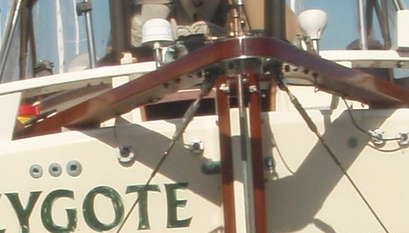
The tiller + rudder is a tenon and mortise joint.

I was picturing the cleats on the tiller as resting against the forward side of the rudder cheeks to prevent the tiller from sliding aft.

Yes, that’s right. You’ve got it.

But are you saying there is a hole through the tiller with a tenon sliding through (like the fid in the bowsprit)?

No.

‘Tenon’ is likely a proto-Indo-European word that stretches back a long way and holds language histories together. The word was borrowed into English from Old French and in those and related languages (all the way back to Greek) means 'something that holds on, holds things together.

Think of closely related words in English, such as ‘tenant’ (a person who holds onto the landlord’s property temporarily).

The PIE original word, meaning the root word that we can just barely trace to a multi-cultural mob of peoples living near the junction of the Eurasian steppes and the little peninsula that sticks to the west off the Eurasian continent, clearly had the ‘ten’ sound and probably meant ‘to stretch’ (hence English ‘tension’.

At least one of that mob of polyglot PIE speakers moved south into the Balkans, carrying the word and concept with them.

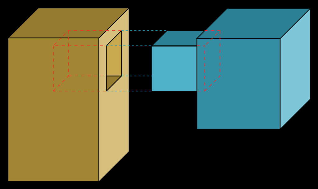
The traditional cabinetry mortise and tenon joint is the attached image (mortise and tenon.jpg). The stock on the right (in blue) could be stone or timber. The worker cuts into that stock to create shoulders and the thin tenon (the protruding piece - which is like the thin neck protruding from the shoulders of the wider trunk.).

In the case of a tiller, you cannot afford to cut into the stock to make shoulders and a thin tenon. That cutting would weaken the whole tiller; its strength would be determined by the size of the tenon.

So for a tiller (in contrast to most cabinetry mortise and tenon joints), strength is everything. Most cabinetry is not about massive leverage at the joint. The tiller/rudder joint is all about leverage.

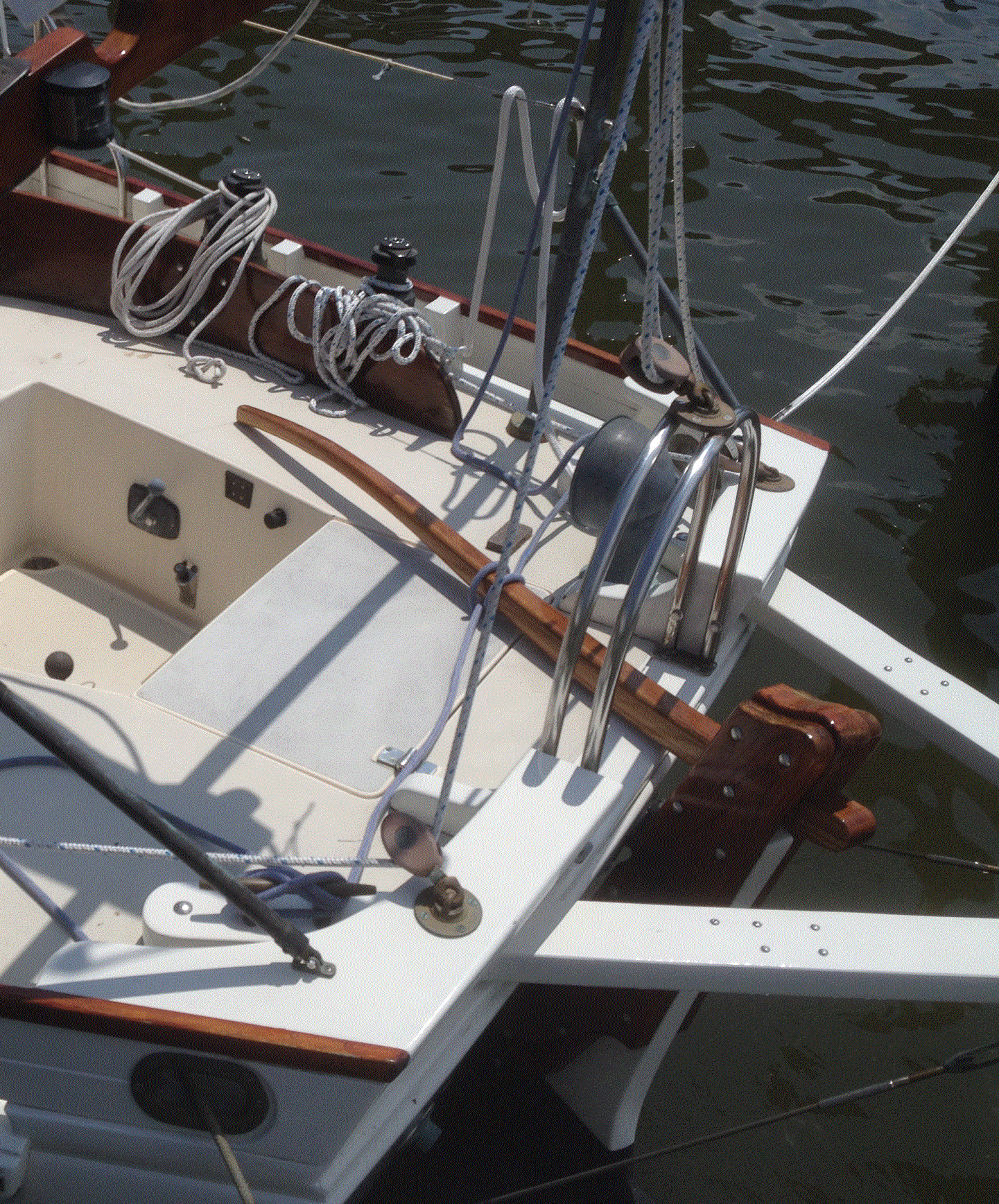
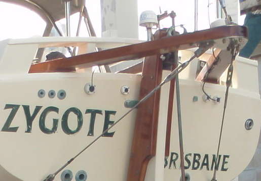
The whole tiller is the tenon. And the added cleats (to stop the tiller moving aft) are the shoulders of the piece.

Now let’s consider ‘mortise’. The English word comes from the French, but this time not directly from a proto-Indo-European (PIE) word that became Greek, then Latin, then French before English.

‘Mortise’ is more likely a Semitic word, with its oldest surviving descendant probably being Arabic ‘mortazza’- ‘to be fastened together’. That Arabic word gets left behind in Spanish as ‘mortaja’ - ‘a socket to accept a pin or a tenon’.

So we can call the slot in the inboard end of the bowsprit a mortise. But we call the peg we put through it a fid, not a tenon. The fid acts as an added shoulder, to bear compression forces transmitted to the bowsprit from the headstay and bobstay. So the fid is not joining, not making a joint. It’s acting as a shoulder to interfere with forces pushing the bowsprit aft.

The fid in the bowsprit is acting almost the opposite way to the tiller retaining cord running through the drilled hole in most BCC tillers. The retaining cord (or the throughbolt that you have penetrating both your rudder cheeks and your tiller) acts to interfere with any tension force pulling the tiller forward.

In the case of your BCC, you likely do not have shoulder cleats attached to your tiller, because that throughbolt does two jobs: stopping the tiller moving aft (the job of shoulders attached to other BCC tillers); and stopping the tiller moving forward (the job of a tiller retaining cord on other BCC tillers).

So your throughbolt is a neat solution. It’s a more expensive option (than a length of short stuff and two small cleats plus wood screws), but neat. Keeping it as a throughbolt, or changing it to a throughbolt held in place by a split pin, ring, or whatever, is also a neat solution that gives your BCC its own character.

Thanks Bil! That all makes perfect sense. I also appreciate the etymology lesson! =)

The bolt hasn’t been a bad solution except that it makes it much harder to remove the tiller. I have looked for long clevis pins as you mention above, but they’re hard to find in stainless (impossible in bronze) in the length necessary.

Since we’re replacing the rudder cheeks and tiller right now, we have the freedom to change with no impact.

Cheers,
Mike

The bolt hasn’t been a bad solution except that it makes it much harder to remove the tiller.

If the throughbolt you have there now is easy enough to withdraw (once the nut is removed), why not keep it?

The throughbolt you have is a neat way of replacing (1) cleats acting as the shoulders to the tiller, to stop the tiller moving aft; and (2) a tiller retaining cord.

If it were my boat, I’d be tempted to keep it that way. I’d either (1) keep the throughbolt with nut and washer; or (2) discard the nut, drill a small diameter hole through the threaded end of the bolt; and then either buy a stainless steel cotter pin or ring, or make up a cotter pin from monel wire or copper wire.

For that matter, you could make a new tiller retainer pin that sits in the same place as your current throughbolt, such as by purchasing a length of bronze rod (perhaps of a ever so slightly slimmer diameter to your current throughbolt, so it slips in and out of the same hole more easily) and adding a washer and cotter pin to each end.

Since we’re replacing the rudder cheeks and tiller right now, we have the freedom to change with no impact.

For sure, if you’re replacing both, you could choose to build a new tiller and drill a hole for a tiller retaining cord and make cleats to act as shoulders on the tiller.

If your current tiller is still serviceable, I’d suggest keeping it as either (1) an emergency tiller; or (2) a parking tiller (if I leave Z for a long time, I usually install a parking tiller, a much simpler construction than the sailing tiller to keep the sailing tiller out of the sun and weather).

Bil,

Apologies for the delay. We’ve gone back and forth on this but finally decided, as you mention above, to keep the hole in the cheeks and tiller as the simple stop. Now I just need to find a long enough clevis pin to make it easy to remove.

As a note- Yes, we will definitely be refinishing and keeping the old tiller. It’s a bit the worse for wear but can certainly make an acceptable emergency tiller once properly refinished. I chuckled at your ‘parking tiller’ idea, which is great. Beth (my wife) will be making a full cover to protect the varnished tiller and rudder cheeks, but if we need to, we may use a piece of PVC as our parking tiller.

We should have photos available soon to share with everyone.
Cheers,
Mike

With the Freehand Steering System, part of the beauty is to have the quick option of removing the tiller…we do this by drilling a hole in the tiller aft of the rudder and insert a 6 inch line with a permanent knot on one side and when in use a overhand knot on the other, when not wanted, just untie the overhand knot and remove both the line and the tiller…easy peasy, no hardware. Mike Anderson

I used a piece of 1 in stainless shaft material cut to necessary length with holes at the ends to accept ‘fast-pins’.
I drilled holes in the tiller and rudder head and epoxied in a short pieces of pvc pipe which has an ID of 1.029. The pin fits perfectly and stops any wear of the shaft on the wooden tiller.

1 Like

Bil, I agree- you have been a marvelous source of information for me and for others. Thank you. Regarding the wooden cleats that prevent the tiller from pushing aft too far, I wonder whether when you have fitted the tiller whether it pivots up and down. My BCC is one secured with a bolt through the rudder cheeks, giving it some up and down motion which i find convenient. I am considering making it removable but if the cleats shove up against the rudder itself, it seems to me that it could not pivot on the bolt.