SSB/HF backstay arrangements

Hello All,

I’m installing a HF auto-tuner and preparing to chop up my backstay and insert insulators. I’m planning on using norseman or stalok insulators; and use wire/fork or wire/eye fittings rather than wire/wire, such that there are only 2 wire compression joints and the whole backstay becomes a radiator. I’m planning on using stainless steel lifeline wire (maybe vinyl coated) to connect the auto-tuner (mounted in the lazarette on the transom) to the base of the backstay. I have not yet checked the total length of this wire and whether it conflicts with any of the likely staple frequencies. Does anyone have any words of wisdom, success stories, or tales of woe from past insulated-backstay projects?

thanks,
Jeremy

Hi Jeremy,
I just added a SSB, I didn’t want to chop my backstay so on the recomendation from a guy who does this for a living I am installing a Gam / McKim Split Lead Antenna. I have yet to try it out but it was highly recomended for what that is worth.
Jonathan

Jeremy,
Shaula’s exhaust from the Yanmar 3GM30F results in lots of salty spray on the end-of-the-boomkin ss plates. If you put the insulator at the very bottom of the backstay, I suspect you might get some of your signal going to ground if you run the engine while transmitting. Our lower staylock insulator is about 6’ above the boomkin.

If I were you, I would use stranded copper wire between the tuner and the backstay. Although special high voltage insulated wire is what the professionals use, I’ve used regular Anchor brand wire before (about 12 AWG) and it worked fine.

How are you grounding the tuner? Lots of copper foil?
Dan

Ahoy Jeremy, my BCC “Calliste” as a used boat , came with a ICOM SSB already installed.

I have used that rig, time and time again, it has saved my bacon, especially when Bil of BCC Zygote, while in Penang, Malaysia, sent me daily weather forcasts, over Sailmail, even as I was at sea , and, approaching Bali, from Oz, after the bombing there in 2002.

As a single hander, back then , you can not even know, how much it was a comfort, to read Bil’s prognastigation of weather and political reports, while I was onroute and otherwise out of touch, at sea.

I heartedly support a SSB rig onboard, for cruising away from home waters, while on route to unknown foreign ports, and even while visiting them !

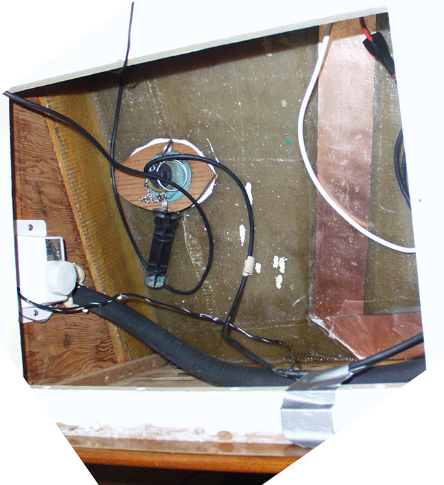
My Icom tuner is mounted as you plan, on the transom, in the lasserete, but the factory installed 3" wide copper conductor and bronze screening , thru-out the hull as a R F ground, was a bad idea. It was f/g’ed encapsulated on the inside the hull, which later proved either a bad idea or a bad installation, because condensation entrapped along the 3" tape line and all along the bronze screen , corroded that copper, and entrapped moisture all along that bonding strip and screening .

My take though not proved would be to drop over the side a bonding plate, to act as a R F ground, then take it back up onboard, when not in use, even while underway !

To have that “sailmail” coms, while underway is very precious, and when out cruising , becomes invaluable .

It is worth every effort to get it, onboard, if knowledge and communication, is of interest to you.

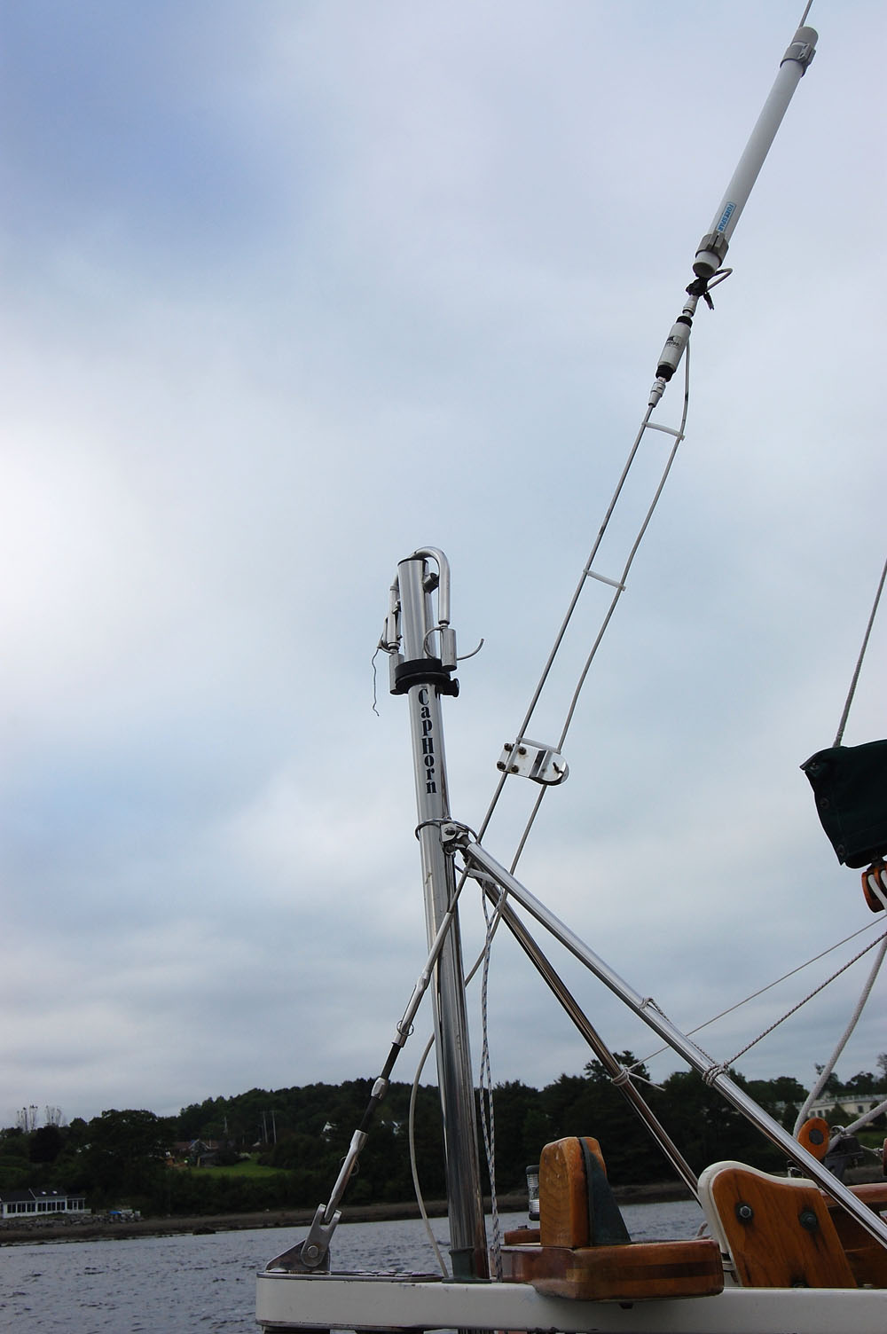
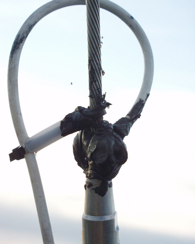
My back stay has Norseman insulators, and the tuner was able to adjust the visable radio output to compensate for an unconventional length antenna .

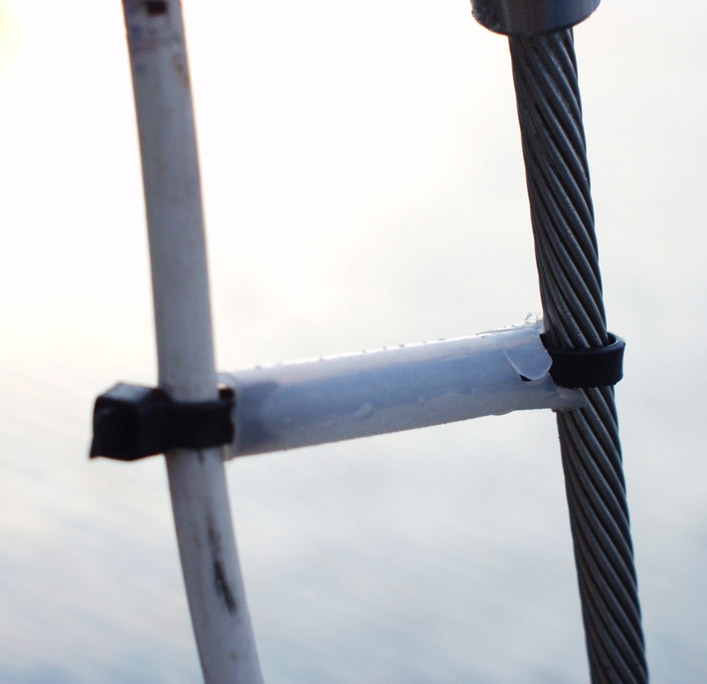
I never needed to use my lifelines as antenna extensions, and my life lines are 1 X 19 ss un-coated wire , for reduced maintaince.

IMO , if you are doing cruising in unknown foreign waters, you won’t be dissapointed to use your SSB and it’s email as coms, onboard your boat !

I haven’t used GRIB files for weather info, but many others have and swear by that too !

Douglas

When I installed IDUNA’s ICOM 802 SSB with an AT 140 tuner, I used GTO 15 wire to connect the tuner to the antenna. This is available at most radio supply stores. GTO 15 is a silicone insulated wire designed for high voltage application.

Our tuner is mounted in the lazarette on the starboard side. When I ran the GTO 15 cable, I added a service loop inside the lazarette to ensure I would have extra cable should I need to cut the end connected to the backstay because of corrosion. Before I connected the GTO 15 cable to the backstay, I tinned the end then used a clamp tight tool to seize the end to the backstay - http://www.clamptitetools.com/. After making the connection, I coated the connection with liquid electrical tape then wrapped the connection with 3M electrical tape. This treatment was followed by another coating of liquid electrical tape.

For a grounding plane, we connected the tuner to a Dyan Plate using a 2" wide copper strap. This was held next to the hull with 3M double mushroom lock “velcro.” This is available at Radio Shack under their brand name. The cost is about $4 for three sets vs. $7 for two sets at the “evil empire” marine store. The copper strapping only needs to be next to the hull but does not have to be in contact with the hull. When making your ground connection only connect the tuner to ground. The radio is grounded to the tuner via the connection cable. If you connect both the radio and turner to ground plane, the radio becomes “confused” and may not transmit properly. Ralph at United Radio, Baltimore was most helpful with the installation. United Radio services and installs electronic on ships. This is where I purchased the GTO 15 cable, copper strapping and end fittings. He also taught me the proper method to solder the Amphenol PL-259 connectors to the coaxial cable.

We normally transmit on low power and have contacted friends in Bermuda, as well as up and down the east coast.

Cheers,

Rod

Had a second thought, when using the strobe, the charging and discharge, interference is audable on the SSB , and I had to switch off my flourescent cabin lights, and just use incandescent or LED cabin lights when receiving on SSB chanels.

Douglas

Hello All,

Regarding the feedline from the tuner to the backstay, I’m not sold on the GTO15 stuff. I figure the antenna is SS rigging wire… by using SS lifeline wire I’m merely extending that same material to the tuner.

The grounding is going to be more of an experiment… I plan on running foil. I have a brush on the shaft which is through bolted on the hull - zink teardrop on the outside, brush on the shaft on the inside. I might run the foil to these bolts first - to get a good wet ground. Then to the engine; then to the lead. I have a lagscrew punched into the lead which I used with my previous HF rig. The boat has a 1 sq ft solid bronze plate screwed into the lead on the underside - so the lead is well grounded. I take my lightnight ground into the lead as well (via lag screw). I have a wood stick, so I tend to worry about lightning - splinters=bad.

I also intend to run a long wire along the hull to deck joint from the tuner grounding nut to the bow. I also have some ribbon cable… which I might use for this duty - cutting the ribbon at intervals so that there are actually multiple conductors each cut to a particular wavelength. I need to refresh my brain on that option and determine what the useful/relevant lengths are. The idea, as I recall, is that these wires essentially give the antenna some hope of operating as a balanced antenna rather than just an unbalanced long wire - thus reducing the load on the ground system.

My previous rig used an inverted vee, which I hauled up a spare halyard to the second spreader, with one end of the inverted vee at the bow and stern. this is a balanced antenna - which doesnt really need a ground at all. It worked exceptionally well. This time around, I’m hunting for an antenna thats always ready… I’ll probably still lug the vee - but will keep it as a backup.

Regards,
Jeremy

Hello All - I’m still tracking down options and part numbers. One option that occurs to me is to rig the insulators like big toggles (eye on one end, fork on the other), so that the insulators are not permanently attached to the backstay at all. For installation, I’d need to cut my backstay in just one spot (to shorten it) and remount my existing norseman terminal.

On the lower end, the sequence would be boomkin eye fitting, to toggle, to turnbuckle, to insulator, to norseman terminal, to wire; and at the upper end it would be masthead fitting, to insulator, to norseman terminal, to wire.

This would allow for easy replacement of the terminals without altering the wire segment. And I only have to redo one swageless fitting.

Jeremy

Jeremy,
I think that you’ll find that using swageless fittings is so easy, that reducing their number on the backstay shouldn’t be a big priority. Granted, they are a bit expensive, and leaving out the 2 that are usually used to space the insulated segment away from the masthead and boomkin will save a few bucks. However, on a BCC, both the mast and boomkin plates are grounded to the ocean through their stays and chainplates.

I think that by omitting the spacers, you will loose some of your transmitted signal to the adjacent (grounded) metal of the mast and the boomkin plate. I don’t know what the effect would be on reception, but I’m guessing it wouldn’t help. The money saved is a small percentage of the cost of complete HF installation.

I’ve read that the voltage on the antenna can be very high in places (nodes)-- 1000’s of volts! That’s why it’s best to use GTO 15 high voltage wire (between the tuner and the antenna), which is designed for those voltages. It’s $.63/ft at Fisheries Supply. The high voltage is why the bottom insulator is usually installed high enough so that the insulated segment can’t be grabbed by someone during transmission.

High frequency electricity used in radios behaves a lot differently from the low voltage DC electricity that we are more used to dealing with. Good luck, and please keep us informed.
Dan

BCC #59 Shaula

I agree with Dan and that is the approach we used a few years ago when we installed an ICOM 802 and AT140 to Itchen. There is a rather extended discussion of all this in archives (2005), but to summarize:
We cut the backstay and installed Norseman swageless insulators a couple of feet below the masthead and about head height above the boomkin.

We ran GTO15 from the AT140 to a bronze grounding clamp just above the lower Norseman insulator – drilled and tapped to accept a ring terminal attached with a machine screw and then liberally covered with paint-on vinyl waterproofing goop. We then made a bunch of +/- 3" standoff insulators using cable ties and 3/8" polyethylene tubing fitted to keep the GTO15 parallel to but far enough from the lower grounded part of the backstay to minimize signal loss.

I ran 20’ or so of 4" copper foil from the AT140 along the hull and soldered and screwed tabs from it to both water tanks and with lag bolts into the forward and aft lead keel castings. Gary Jensen from Dockside Radio suggested much of this helped with the Pactor setup and also did a signal strength check for me while I was in his SW Florida area.

This has been a totally trouble free installation and we have used it routinely for Sailmail using a PactorIII modem and also communicating with Chris Parker’s weather net and the morning Cruizheimers net. We put out a good strong signal by all reports.

While researching this before deciding on the installation I came to the conclusion that there’s more than one way to skin this particular cat and that much of the endless discussion is fed by the fact that if you get it at least half-ways right you will receive and transmit adequately most of the time.
Several experienced ham operators have pointed out that RF ground is VERY different from DC or AC ground – and RF ground does not have to actually contact the seawater to function well. All you need is adequate ground area along the inner skin of the hull or tanks and keel to couple very effectively with the water outside. That’s what we did and it works well and avoided drilling more holes through the hull!
One last thought – with the ICOM 802 one can mount the head unit away from the transeiver and so I put it in a cabinet on the bulkhead at the forward end of the stbd bunk. Much more comfortable to sit on the bunk and twiddle knobs and take notes at the saloon table than doing it standing up and hunched over the refrigerator/“Nav Station” where the SSB is most often located. It is also out of the way of anyone working in the galley.

svshaula Wrote:

Jeremy,
I think that you’ll find that using swageless
fittings is so easy, that reducing their number on
the backstay shouldn’t be a big priority.
Granted, they are a bit expensive, and leaving out
the 2 that are usually used to space the insulated
segment away from the masthead and boomkin will
save a few bucks. However, on a BCC, both the mast
and boomkin plates are grounded to the ocean
through their stays and chainplates.

I think that by omitting the spacers, you will
loose some of your transmitted signal to the
adjacent (grounded) metal of the mast and the
boomkin plate. I don’t know what the effect would
be on reception, but I’m guessing it wouldn’t
help. The money saved is a small percentage of the
cost of complete HF installation.

I’ve read that the voltage on the antenna can be
very high in places (nodes)-- 1000’s of volts!
That’s why it’s best to use GTO 15 high voltage
wire (between the tuner and the antenna), which is
designed for those voltages. It’s $.63/ft at
Fisheries Supply. The high voltage is why the
bottom insulator is usually installed high enough
so that the insulated segment can’t be grabbed by
someone during transmission.

High frequency electricity used in radios behaves
a lot differently from the low voltage DC
electricity that we are more used to dealing with.
Good luck, and please keep us informed.
Dan

BCC #59 Shaula