SSB

Because the BCC has a boomkin and the backstay is therefore far removed from the cockpit area I’m curious if any owners who have a SSB have felt it necessary to have the lower insulator high above the bookin ?

I’m adding an SSB and considering placing the lower insulator directly above the turnbuckle. My thought being that the longer the ‘insulated’ section of the backstay the better and with the stay location being so far aft the likelyhood of anyone getting a RF burn is quite unlikely.

Any thoughts ?

Thanks,

Baba

I had the same idea when I installed my SSB radio. I put the insulator only a couple feet above the turnbuckle. That made the insulated wire length 33 ft which is ideal for HF frequencies. I thought there was minimal risk of anyone holding the backstay while the radio was transmitting. It also makes the transmission wire easier to service since it attaches so much lower.

Ron Thompson
Ho’okahiko 97

My gaff rig is backstayless so had to find an alternative. Here is a SSB antenna that floats inside a length of double braid with core removed. Could be interesting even for boats with a backstay.
http://www.ropeantenna.com/

Combined with the KISS counterpoise, makes for a simple installation.

Thanks Ron. I spoke with a rigger about putting it very low and he thought it was a terrible idea. He said nothing less than 5 or 6 feet above the bookkin would do. Just knowing that you’ve done this before me makes me feel much better :slight_smile:

David that antenna inside that double braid looks like a great solution for someone who has no backstay. I did get a chuckel out of the last paragraph on that site though. They suggested having one as a spare antenna in case you mast comes down. I wonder what you’d suspend it from if you had no mast ? :slight_smile:

Thanks !

Baba

Baba,
I guess if you lost your rig and your primary backstay antenna with it, your spare rope antenna strung from bowsprit to boomkin could get you out of a bind. Works fine horizontally.

Baba , are you not planning to use an antenna tuner ?

Hello dwkayks,

Yes I will use a tuner. I hope to intend to install an Icom M802 transiever and an Icom AT-140 tuner.

Baba

I fitted the lower insulator on the backstay at about the same level as the bumpkin gallows or about 2-3 ft above the backstay turnbuckle. I connected the GTO-15 high voltage wire leading from the turner to backstay just above the insulator. I also built 2" standoffs from 1/2" diameter CPVC tubing to hold the GTO-15 away from the backstay. One zip-tie is used to connect the standoff to the backstay and another to connect the GTO-15 wire to the other end of the standoff.

Because of the BCC’s bumpkin and gallows, the risk factor of a crew member holding onto the backstay while transmitting, in my opinion, is very, very low.

Regarding the “pro” rigger, he/she is always concerned about liability. Further modern boats have inboard rigs and the risk factor of a crew member holding onto the backstay is significantly higher than that for the BCC.

Rod
IDUNA

Regarding insulation of the ICOm 802 and AT-140 turner.

ICOM shows both the transceiver and turner grounded to the ground plane. The 802 transceiver is grounded to the AT-140 turner by the cable connecting the two together.

The owner of United Radio Services (ships & tug electronics) told me to only ground the turner to the ground plan. If you ground both units, you will have problems transmitting and receiving. This was confirmed by a cruiser who grounded both units then removed the ground from the 802 to the ground plane.

Iduna uses a separate dynaplate for her ground plane. A 2" wide copper strip connects the turner to the plate. It is not necessary to imbed the copper strip into the hull. I used 3M double latch “velcro” (Radio Shack) to hold the copper strip in place.

Rod
IDUNA

There are lots of ways to skin the antenna cat. I think that the main disadvantage to placing the insulator close to the boomkin is its greater exposure to salt water. In choppy weather, the boomkin is constantly wet, both by spray, and by exhaust when motoring. Salt water could conduct part of the signal from the insulated part of the backstay down to the ocean through the boomkin hardware. The boomkin tangs on the hull are often (always?) submerged when underway.

Even when the attachment is made higher on the backstay, keeping ahead of corrosion at the Cu wire to SS 1x19 wire join is a challenge. It’s hard to seal off the SS wire from saltwater that runs down the wire. I crimp on a lug on the Cu wire, mash it around the SS wire, clamp them together, and wrap it all in self-amalgamating rubber tape. I undo (cut off) the tape every year or two and check for corrosion. I’ve replaced the wire several times in the last 27 yrs.
Dan

  1. Antenna length

Aiming for a longer antenna length by placing the lower backstay insulator as low as possible is like chasing a mirage.

That’s because the entire run of wire, the GTO-15 feed wire from ATU to backstay + the insulated run of the backstay, is the length of the antenna.

If the lower insulator was placed 2 metres above the turnbuckle, you’d need a longer feed wire. And the total of feed wire + backstay would be not much different than if the lower insulator was placed just above the turnbuckle.

In practice, no one runs the bare minimum of feed wire. That’s to allow for what Dan reported - the need every year or three, to snip off corroded wire from the feed wire.

If you used coax instead of GTO-15 as your feed wire, the picture would be different.

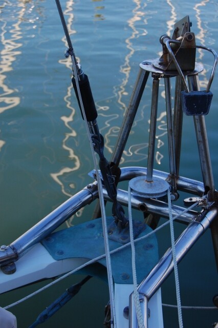
Zygote has 3 metres of GTO-15 feed wire + 8.7 metres of insulated backstay, giving a total antenna aperture very close to 12 metres. Theoretically the ATU should be less successful, because of antenna resonance, tuning in the 24 metre and 12 metre radio bands (12MHz and 25 MHz). We’ve not noticed that (and, like Dan, our feed wire gets a little shorter every now and then).

  1. Protecting the crew from RF

Voice work is different from PACTOR modem work. A PACTOR modem drives the SSB transceiver quite hard (in terms of transmission power). Silence between words makes up a big chunk of voice work.

The result is that for voice work, you likely only need worry about RF burns from someone touching the antenna when you’re transmitting. Which, as Rod points out, is unlikely.

But PACTOR work makes it worthwhile to consider the RF bathing the cockpit.

Typical of big Government Euro-socialists, the nanny state of Australia came up with guidelines and regulations about a decade ago. If you’re interested, point your browser to http://www.arpansa.gov.au/Publications/Codes/rps3.cfm and download the Standard (RPS No. 3, about 2.1 MB) from the top link.

We went to the trouble of modelling the RF transmissions on Zygote (backstay at 63 deg to the horizontal, lower insulator 2.8 m above sea level, peak transmission power, head of a person seated at the tiller located 1.25 m from the antenna at 111.5 degrees from the line of the backstay … etc you know the drill) and produced a document, which is likely on board in the folder with Zygote’s apparatus license, to cover ourselves.

We used free software, written by hams for hams, to model the RF propagation from the antenna. If you’re interested, your favorite search engine will find it. I’ve forgotten many of the details (eg I’ve forgotten whether it’s a good or a bad thing to have your antenna closer to the water surface; I’ve a rough memory that keeping my head more than 1.25 m from the antenna is a good thing).

The document said we would never let a member of the public stand on the water surface within two metres of the transom when transmitting. And similar motherhood statements. No govt inspector has asked for that document (but they could! all that is necessary is a couple of complaints from members of the public).

And to protect ourselves, we adopt a practice of minimising our presence in the cockpit when doing PACTOR work. Meaning minimising crew in the cockpit and keeping them forward and on port (the ATU and feed wire run on starboard).

Cheers

Bil

Bil Wrote:

We went to the trouble of modelling the RF
transmissions on Zygote (backstay at 63 deg to the
horizontal, lower insulator 2.8 m above sea level,
peak transmission power, head of a person seated
at the tiller located 1.25 m from the antenna at
111.5 degrees from the line of the backstay …
etc you know the drill) and produced a document,
which is likely on board in the folder with
Zygote’s apparatus license, to cover ourselves.

We used free software, written by hams for hams,
to model the RF propagation from the antenna. If
you’re interested, your favorite search engine
will find it. I’ve forgotten many of the details
(eg I’ve forgotten whether it’s a good or a bad
thing to have your antenna closer to the water
surface; I’ve a rough memory that keeping my head
more than 1.25 m from the antenna is a good
thing).

FWIW, I found the document I wrote after doing that modelling. In my modelling, I took the view that Zygote had no feed wire and that the antenna was made of the GTO-15 and the insulated portion of the backstay. The result was a table addressing points raised by the Aus govt document (indicated by Letters in brackets) and looked like this (with the conclusion that people should be kept 1.4 m away from the antenna when the SSB set is being driven hard):

Evaluation B: MF/HF

  1. Average power output, Watts: (A) 20 W
  2. Average power output, converted to dBW: (B) 13 dBW
  3. Feed line loss specification: (C) 0 dB per 30m
  4. Feed line length, in metres: (D) 0 m
  5. Calculated loss, in decibels: (E) 0 dB
  6. Other feed line components:
  7. Losses due to other feed line components, in decibels: (F) 0 dB
  8. Average power fed to antenna, in dBW: (G) 13 dB
  9. Average power fed to antenna, in Watts: (H) 20 W
    10 Antenna description: long wire antenna composed of 3.3 metres of GTO-15 wire (14 AWG, insulated with Tuf-Hide; the conductor has a diameter of 9/64? or 3.57 mm, a cross-section of 2.08 mm2, and an impedance of 2.5 Ohms/1000 feet) and 8.7 metres of the 7.1 mm (9/32?) 1x19 stainless steel (316) wire backstay, for a total length (or aperture) of 12 m
  10. Antenna gain: (I) 2 dBi
  11. Antenna efficiency factor: (J) 1
  12. Average total power radiated by antenna, in Watts: (K) 20 W
  13. Minimum separation distance required from antenna: (L) 1.4 m
  14. Measured distance from antenna to nearest place where persons may be present:
    (M) 1.55 m

Cheers

Bil

Hello Baba/All,

I placed my insulator right above the turnbuckle and am happy with this arrangement. I like that it eliminates 2 rigging wire terminals. The lead wire from the auto tuner to the backstay is radiating - so I didn’t see much safety benefit in elevating the lower insulator as you need to keeep crew away from the lead wire as well. I used vinyl coated stainless steel lifeline wire for the lead wire. This eliminates concern about oxidation and sealing the point of attachment to the back stay. And the material is readily available at reasonable cost. I did the same thing at the top end of the backstay. One end of the upper insulator is a wire terminal, and the other is a eye that engages the toggle at the mast head. So overall i ellimated 4 rigging wire terminals.

Regards,
Jeremy

and here is the pic of the top end