In the spirit of forewarned is forearmed, here’s more detail to follow Tom and Jill’s alert to other members of the BCC-28 fleet with Yanmar 3GM30F engines.
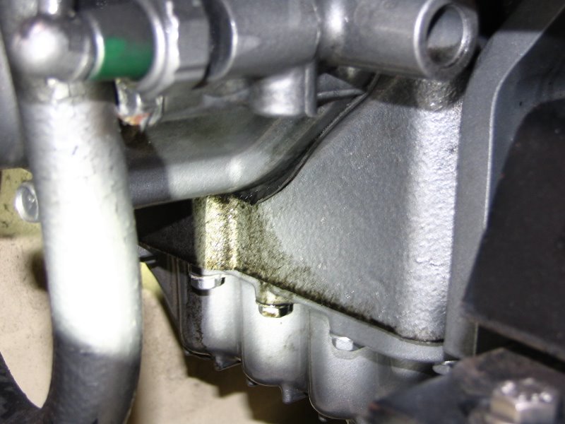
The problem with the gasket at the timing cover exhibits by two signs: black engine oil in the oil pan under the engine; and protusion of the gasket from the lower port side (at about 5 o’clock, looking at the front of the engine). See Tom and Jill’s photo timinggearcovergasketfailure.JPG (75 KB ).
The problem is not a one-off. As Tom and Jill noted, one UK Yanmar dealer (Marine Power Ltd.; Dave Swain, a marine engineer at Marine Power Ltd. runs an informative website and forum for Yanmar owners at http://www.yanmarhelp.com that was originally started by Dick Tucker, who had been Service Manager for a NZ Yanmar distributor) repaired 25 engines with the exact same problem from the Sunsail (UK) charter fleet.
The symptom of the problem can be dealt with by replacing the gasket with the steel-reinforced gasket, Yanmar part number 121575-01512. Do NOT use a gasket with part number 121575-01511 - that’s the gasket that was used when assembling the engine and is part of the reason for the failure.
As a result of their experience replacing the timing gear cover gasket on 25 engines, Marine Power Ltd posted, on their internet forum, notes on their repair procedure. I’ve included a slightly modified version of Marine Power Ltd’s repair procedure here, because Tom and Jill found it valuable (it reduced the hours of repair time).
For speculation about the cause of the problem, see section B at the end of this post.
A. Repair Procedure
Parts list: (** see late addition below**)
119305-35151 Oil Filter 19.56
121575-01861 Gasket 6.43
121450-01801 Seal 11.02
128270-01820 Seal 12.14
121575-01512 Gasket 57.79
Total Parts inc GST 117.63
Labor 5.25 hours (2.7 hours working on the engine, 2.8 hours cleaning up the timing gear cover, general clean-up, checking engine operation)
Total 470.00 Cash
(prices in $Aus in June 2007, when $A1 = US$0.84)
-
Shut off fuel cock and batteries (no need to drain fuel or crankcase oil, but it’s an opportunity to change the oil and the oil filter - a new filter is already included in the parts list).
-
Remove the throttle and stop cables.
-
Remove all v-belts, the water hose running from the flexible impeller water pump to the front of the heat exchanger, and the flexible impeller water pump. Loosen the alternator (you’ll be moving it out of the way a few times).
-
Remove the high pressure fuel injector pipes and the fuel supply pipe.
-
Loosen and then raise the high pressure fuel injector pump (F.I.) pump. Marine Power Ltd noted that this step saves considerable time compared to removing the F.I. pump. Remove the idle adjuster assembly and the small plate beneath. This allows you to see the fuel rack on the F.I. pump, which has to be in the mid position for removal. Undo the four F.I. pump securing nuts and set the stop lever to the vertical position - this will put the pin on the fuel rack in the mid position. Split the pump from the timing cover using a fox wedge or chisel, being careful not to damage the shims (the shims set the timing of the injection events). Pry and wiggle the pump and raise it high enough for the rack to be visible above the timing cover and then place a suitably sized spacer (eg a hand tool) to hold it in place.
-
Remove the 27 mm nut and then the main crank pulley wheel. The ideal way is to use a pulley wheel puller. But it can be done without a puller (crudely but carefully) if you screw a couple of 8mm bolts into the pulley so you can lock it with a bar/screwdriver and stop it turning. Then tap around the circumference of the pulley wheel with a leather, wooden or plastic hammer/mallet.
-
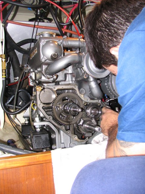
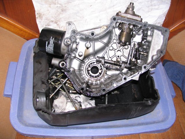
Remove timing cover. It will likely come off halfway and then stick on the crank bearing; additional wiggling will free it. See Tom and Jill’s photos timinggears.JPG (81 KB ) and timinggearcover.JPG (76 KB ).
-
Clean up, remove old gasket.
late addition
8a. replace the 2 o-rings, part number 24311-0001002, on the oil channels between cover & block & gasket, on the port side.
** end late addition**
-
Install new gasket
-
Reinstall cover, making sure that the oil channel o-rings on the port side are properly located.
-
The most important part of the job is to ensure that the F.I. pump fuel rack pin locates correctly in the governor arm fork when you lower the F.I. pump back into place and tighten down. Set the rack to the mid position and the stop lever vertical and visibly check through the side inspection plate aperture that it is correctly located. If not, repeat until successful. If the rack does not locate, the engine will either not start or will start and run away, uncontrolled.
-
Reinstall ancillary parts, pump, and belts.
-
Add oil (if removed).
-
Bleed fuel lines.
-
Start engine. Check and re-set idle speed (the range 825 - 875 rpm if using an accurate handheld tachometer; if using the boat’s tacho, aim for the higher end of the range). An idle speed at the higher end of the range helps prevent excessive ‘death rattle’ vibration and reduces stress on the reduction gear (ie the gearbox).
B. Speculation about the cause of the problem
The protuding gasket implicates excessive internal pressure, from combustion gases leaking out the combustion chamber. The steel-reinforced gasket will likely prevent it happening again. But the newer gasket does not cure whatever is the cause of the excessive pressure.
A compression check on each of the three cylinders will show if any major problem exists. But simply pulling out the oil dipstick and covering the dipstick aperture with a thumb, while the engine is running, will show if combustion gases are blowing by the piston rings (you can do a similar simple test for combustion gas leaking past the valve seats by unscrewing the oil filler cap and covering the aperture with the palm of your hand).
Cruisers (in contrast to day sailors making a sortie from a harbor) tend to idle diesel engines too much (eg when charging batteries) and to run the engine at low speeds (eg around 2200 rpm) to get good fuel economy. Both practices can lead to carbon glaze forming around the piston rings and gluing the rings to the piston, stopping combustion gases getting underneath the rings and forcing them against the cylinder wall to form a good seal.
The glazing problem can be avoided easily: aim to run the engine at higher speeds (2700 - 2900 rpm is not too high; you’re trading off increased bearing wear with reduced carbon deposits). And if running for a long time at low engine speeds, punctuate the low speeds with say 5 minutes at higher speed every hour. Similarly, if you have to idle the engine for any time, give it a 30-second burst at 3,000 rpm before allowing it to cool down again at lower rpm.
If piston rings do glaze and stick, running at higher speeds may free them. In extreme cases, removing the head and physically cleaning the rings and pistons may be required.
Associating carbon deposits around the piston rings with the problem of the timing gear cover gasket is speculation so far! I’m interested in learning more from anyone with greater experience (Marty Chin, where are you?).
Cheers
Bil (with edits to remove typos and make late additions)