Hello everyone, I’m a new BCC owner and this is my first post. I’m currently in a boatyard refit with a looming departure deadline, and I am decommissioning the entire freshwater system due to contaminated and corroded stainless steel tanks.
I am finalising specifications for two Ronco B337 (22gal) tanks. My primary concern is the plumbing bridge between them:
Compartment Length: 75 inches (Bulkhead to Mast Step).
Total Tank Length: 72 inches (2 x 36").
Net Gap: 3 inches total.
Looking at standard BCC diagrams, the 1.5” sleeves are in-line. However, I don’t see how it’s possible to bridge a 3-inch gap with 1.5" hose and barbs.
My proposed solution: Order the tanks with staggered/offset sleeves (e.g., Port-Aft on Tank 1, Starboard-Forward on Tank 2) and run a reinforced hose diagonally using 90° Spears barbs.
Has anyone successfully bridged these tanks in a 3-inch gap using the “in-line” method?
Does anyone have photos or specs for a “Diagonal Bridge” setup they’ve used in this bilge?
I need to submit this order to Ronco by tomorrow to make my launch window. Any insights or “as-built” photos would be a massive help.
This can all be done in the water so Id sloe down and do it right. Silly question but can you not clean the two tanks? 44 gallons wouldn’t last long, you should have close to 75. Sorry I can’t help with this but id focus on a safe launch and do this dockside.
Hi Benji - Mischief (#67 / 1983) has 2 stainless steel tanks. One long tank on top of the lead, and one deep one aft of the lead in the deep bilge. I’m not aware of factory finished boats having 2 tanks on top of the lead - but SLM may certainly have done that with newer boats. If I were in your shoes, I’d make doubly sure Ronco does not a make a longer tank that will fit in the space on top of the lead - so as to avoid installing 2 tanks on top of the lead. I think that configuration would have more capacity. If I were really stuck installing two 22 gal tanks there, I think I would NOT interconnect the tanks, but rather treat them as separate tanks and run the hoses aft to the manifold under the galley floor - and build a new valving manifold to accommodate 3 tanks.
I see this old post from Roger (previous owner of SLM) where he says they did switch from SS to Ronco in 1991 - and he does discuss using two 22 gal Ronco tanks connected together. If the connection was 1-1/2", maybe they just used a short nipple and mated the tanks together before installation. That seems frought with the danger of damage stressing the tank fittings during installation. I don’t think the interconnect needs to be 1-1/2" - that seems over kill. 1/2" or 3/4" would be good enough. The interconnect could then be by hose connecting 90 degree barbs mounted on opposing (port/sb) corners of tanks.
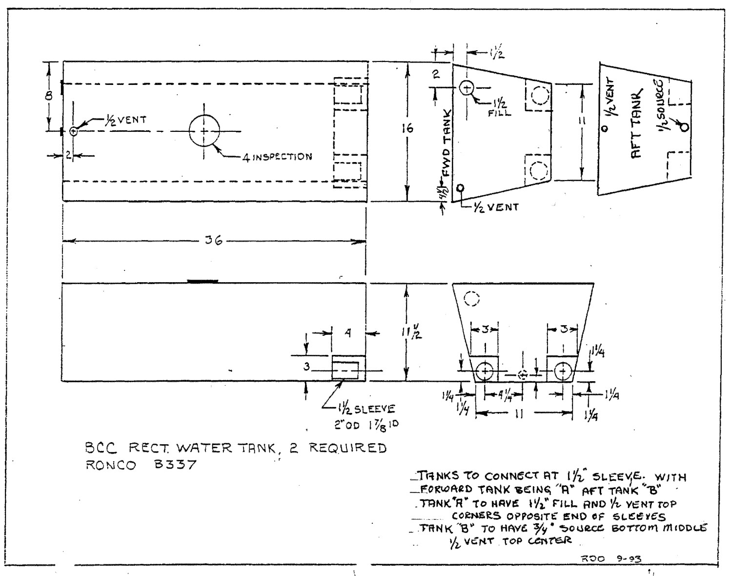
And there’s this diagram of those Ronco 22 gal tanks from the BCC Build Manual. The diagram shows a pair of recessed spaces for 1-1/2" nipples that are used to interconnect the two tanks. Given this space is inaccessible once the tanks are dropped in the bilge, I expect the yard preassemble the pair (installing the 1-1/2" interconnect hoses and hose clamps) and then dropped the assembly into the bilge as a unit.
I would verify that Ronco actually still builds this tank with those recesses. The diagram on the Ronco site shows them - but I’d still check with them.
Dear all, thanks so much for your feedback. Sorry for the delay in responding. I’m at an every-hour-counts type moment. But bear with me because I’m going to be throwing more questions your way.
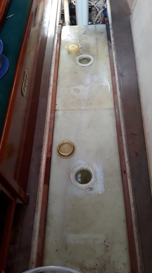
The diagrams are confusing because they’re describing two different units on a single diagram. I did eventually realise that it’s not an exterior fitting but an inset sleeve (tube). So I know now that no gap is required (as in Bil’s pics), but I’m still confused about the vents. I understand that there is a vent on the aft face of the aft tank (B) and on the forward face of the forward tank (A). The vent that’s on the top face, left edge, I assume, only goes on tank A, or is that just a second option to choose from, because that would mean there are two vents on tank A? I’m not an engineer, but I’m assuming that you need a vent on either side of the tank system so there’s always one open during heave and pitch. Now I’m looking at the pictures in this thread, I can see there is no top vent on tank A, so that is helpful. I’ll remove that from the order. Thanks for the help, guys! Both tanks are listed in the current catalogue.
In terms of timing, yes, I am only working on launch-critical items, but this one I really need to order because I have to leave the US by April 28. All the plumbing and everything else I can deal with later.
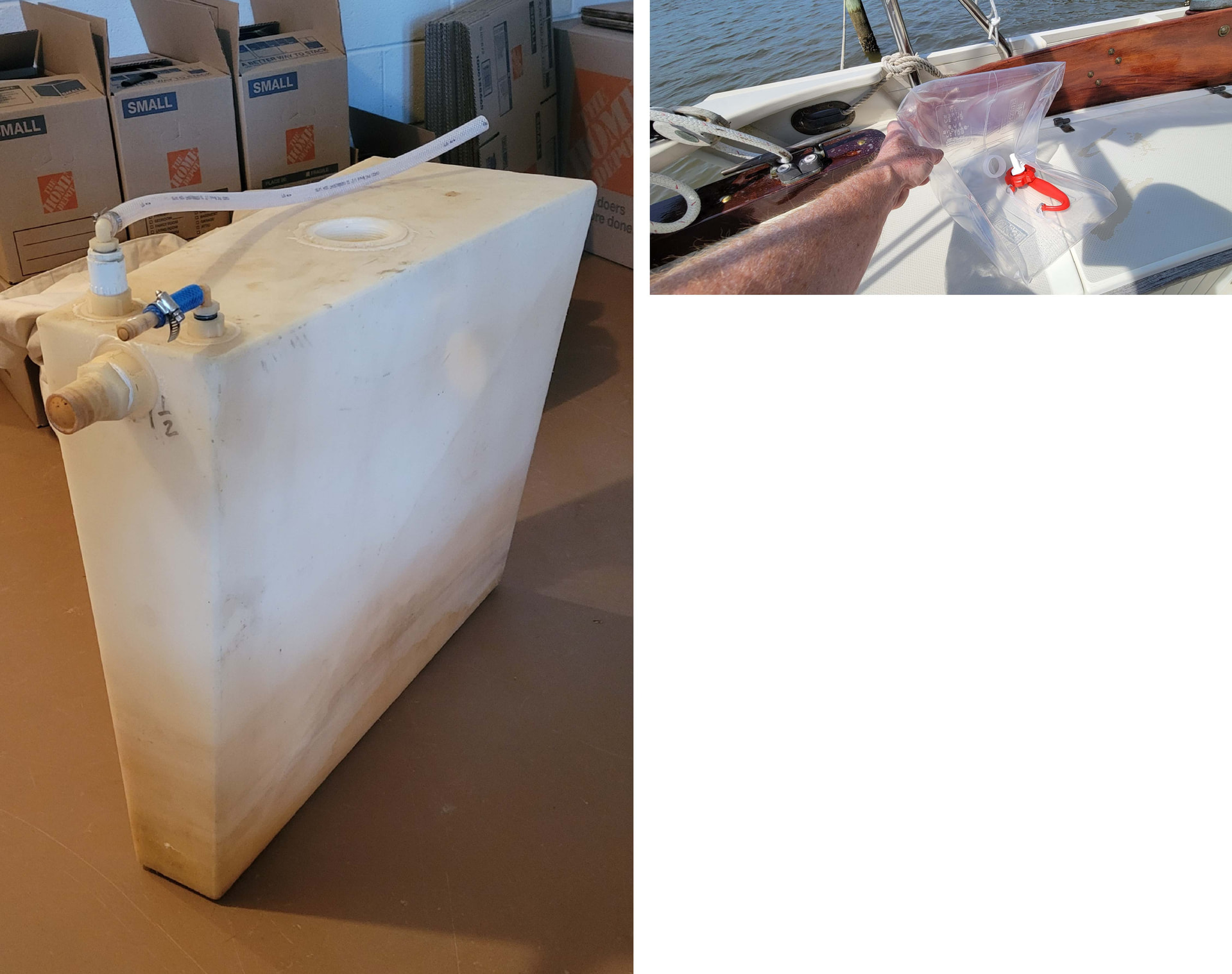
My tanks look exactly like the picture of Zygote. Actually its a picture of MY tanks from the BCC fb group. I have one overflow vent on the rear starboard side of the rear tank. It vents into the cockpit via a hose that runs from the vent to the cockpit. There is small cockpit outlet just in front of the engine throttle control. This was all standard factory stuff for BCC 108. P.S. I removed my vertical tank under the engine. It was not needed. Now I can see the bilge pump.
I recon the diagram erroneously shows a vent on the tank top face. There may not be sufficient room for even a 90 degree elbow between the top of the tank and the underside of the cabin sole board. The notes on the diagram don’t mention a vent of the top face and instead place the vents on the fwd and aft faces. Both tanks absolutely need separate vents.
I see it. Thank you. Any idea where the other vents end up?
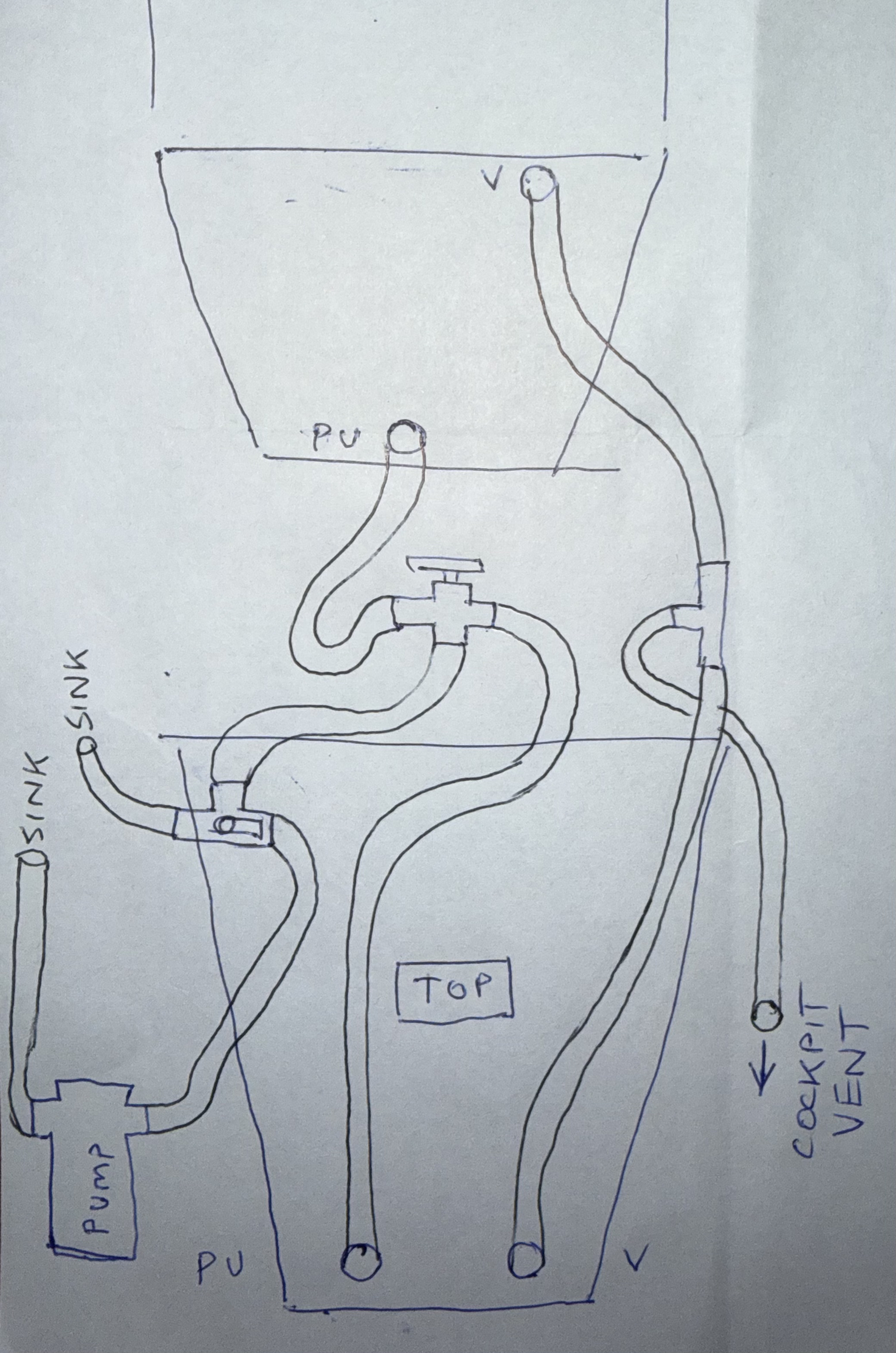
I’m going to order all three tanks and switch Tank B to a top-down pickup rather than a gravity-fed “source” at the base, and connect it to a 3-way valve with the galley wedge tank—mimic the current stainless steel setup.
For the two tanks on top of the keel, only the rear one is vented. Water flows freely between the two tanks so I would agree with that design. It is, after all, just an overflow vent and mostly just vents air. That vent, plus the vent from the vertical tank below the engine, join up with a t-connection. And then, there is just one hose that runs back to the cockpit.
Okay, that’s good to know because I’m looking at the stainless steel tanks, and it looks like there is in fact only one vent at the rear for that long tank (two plastic tanks). The diagram has three vents covering those two tanks. It’s just very confusing because I have to specify the exact components to Ronco.
@MRGEARHA can you verify there is no vent connection on your forward 22G tank? The diagram suggests it’s on the forward face to starboard of the mast. In order for the fwd tank to fill, the air needs to be displaced. The air in the forward tank has no path to the aft 22G tank vent once the water level submerges the two 1-1/2” interconnects, and therefore will not fill completely (eg no more than a 1/4 full) unless it has its own vent - as the air would otherwise be trapped in that forward 22G tank.
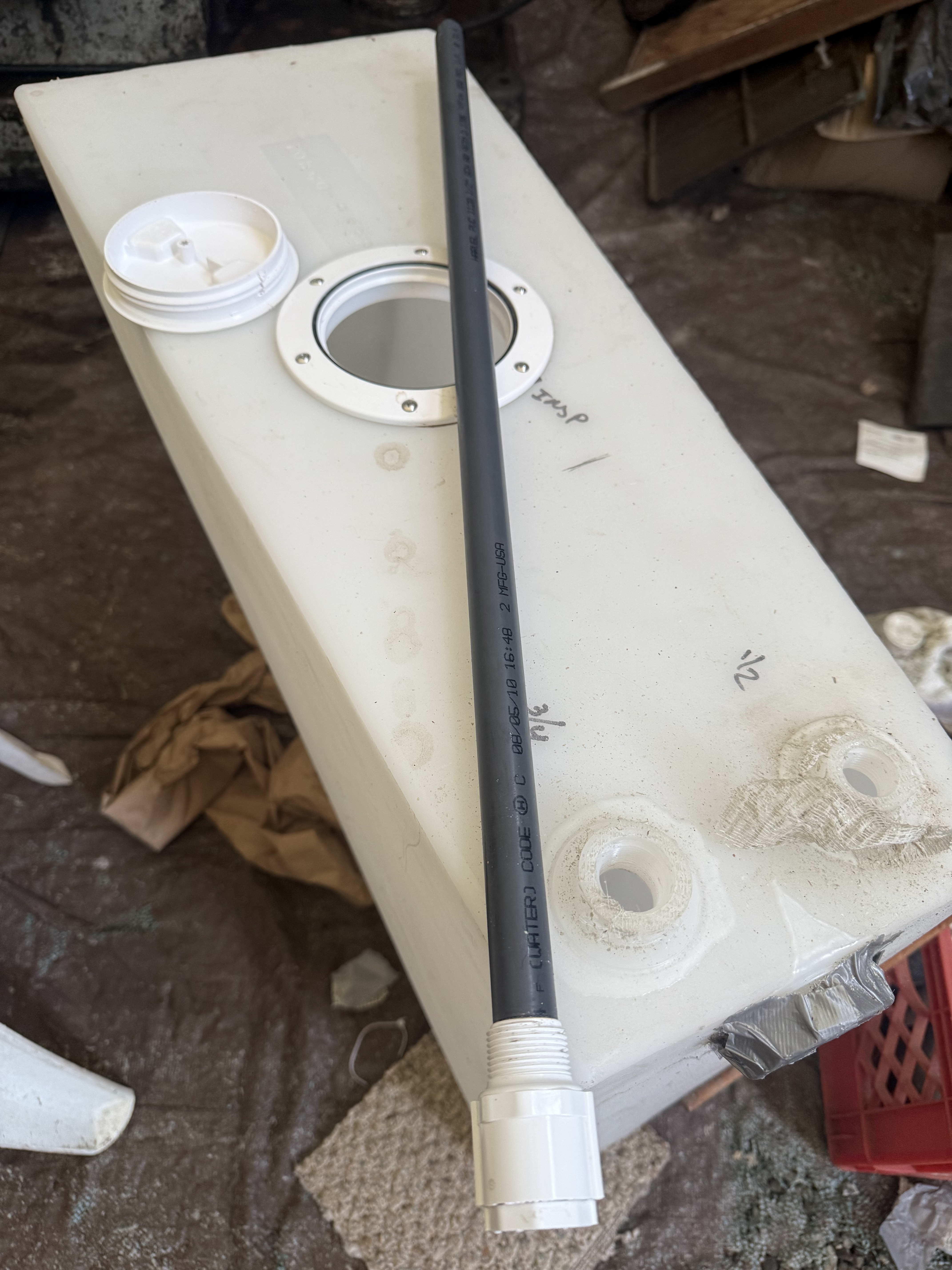
@Benji do you have a design in mind for the dip tube of your top face pickup? Last time I tried that, I found no commonly available hardware that worked for that purpose. I’ve seen some bespoke assemblies built by brazing copper tubing to the brass or bronze NPT fitting attached to the top of the tank. Metal tanks with dip tubes sometimes have the tube fabricated and welded in place during construction of the tank.
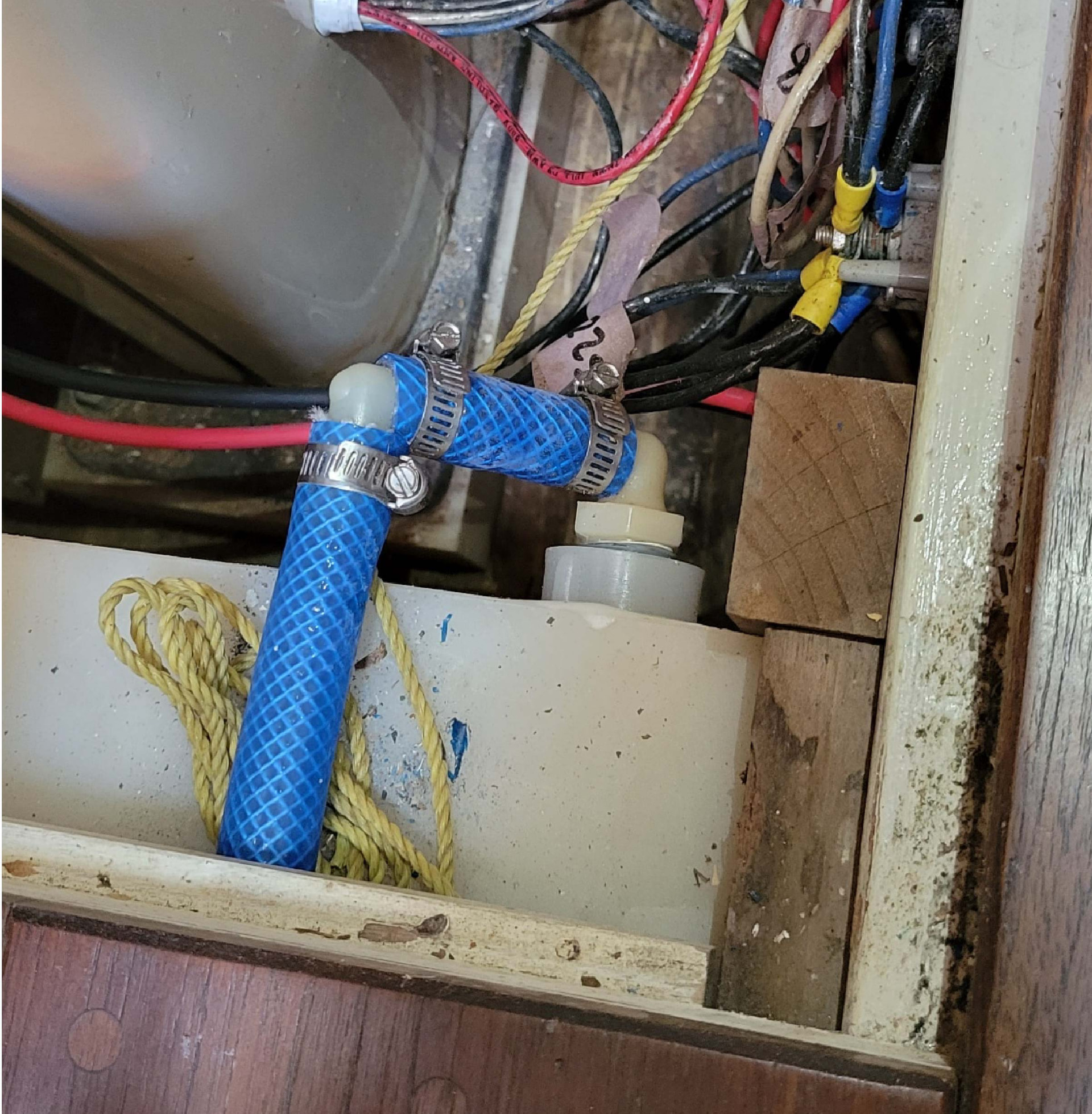
Jeremy, you are 100% correct. How embarassing, I went by memory, but since I am an old fart, my brain is not always there. I will try not to do that again. Atached is a picture of the vent. P.S. my lines are color-coded.
Hi Jeremy. Ronco supply them with the tanks if requested. This is one in the boat yard here. Looks like PVC pipe solvent-welded into a PVC Male Adapter.
Hi MRGEARHA. In your picture, it looks like your B337 tanks sit right up to the underside of the floor. Have you got them blocked up on something? By my calculations, there should be a 5.5" gap there.
They are not blocked up. I have a 13.5 inch space between the top of the keel and the floor. With the tanks installed, there is a 1.5 inch space. The vent runs along that space. Also, for the vertical tank, I can see what looks like a PVC pipe running down to the bottom. It doesn’t appear to be anything special. But, I do not use this tank because I need a place to store 300 feet of chain. That is in addition to 700 feet of nylon line+leader, which I store half in the side locker and half in the chain locker up front. In place of the rear water tank, I have five 5-gallon collapsible water jugs I can store anywhere. Highly recommended by Lynn and Larry Pardey. Made by Reliance, a company in Canada.